Draw BMD SFD for the beam. 29 9 KN 36 KN 18 kNm Support Reactions 12 kNm MB ZMBO - 3 m MB 34 15 91 By shear Diagram KN MB 63 KN-M B IFV D By 369 45 KN - 45.
Solved Problem 6 29 60 Part A Draw The Shear Diagram For The Chegg Com
Starting from end A SF at A RA 29 t.
. 8 ft A B x w w 1 x2 8 kipft 1 8 Prob. C and d 45 kN AFBCBy 75a 3 5 b Ay 15 kN c Fy 0. Mo Mo Mo ZMB 0 ZFV D B Ay L Mo - MotMo D By Ay Ay TBy By MolL L2 Ay Mo L L2 Shear Diagram - Mo -Mo L Moment Diagram Mo Mo N Z -Mo Prob.
2 0 0 M 0 M 2 0 0 l b. See the answer See the answer See the answer done loading. Referring to the free-body diagram of the beam shown in Fig.
6 44 6 45. F B D b FBD b F BDb F y 0. First calculate the reactions R and Rg.
The diagram which shows the variation of shear force along the length of the beam is called Shear Force Diagram SFD. Problem 629 50 SO mm 21 VQ 629 The built-up timhcr is subjected to a 6-kN shear. Draw the shear force and BM.
BA C 2 m 15 m 1 m 2 kNm Equations of Equilibrium. 200M 0 M 200lbf t. Reaction at the support A R A 5 3 7 2 2 6 29 t.
SF just right of C 25 - 5 20 t. Draw the shear and moment diagrams for the simply supported beam. Mechanics of materials chapter 4 shear and moment in beams chapter 4 shear forces and bending moments solution to problem 412 shear and moment.
Uparrow sum F _ y 0quad V0 F y. 200N 2 internal ST notes2 V-M Internal Hinge Inclined Force - Copy 1pdf School University of San Jose - Recoletos Main Campus - Magallanes St Cebu City. Prob 613 Support Reactions.
Mechanics of materials solution manual. A Calculate the shear force and bending moment for the beam subjected to a concentrated load as shown in the figure and draw the shear force diagram SFD and bending moment diagram BMD. 6 40 284 CHAPTER 6 BENDING 6 6 44.
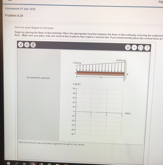
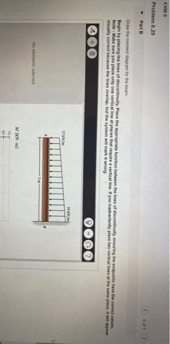
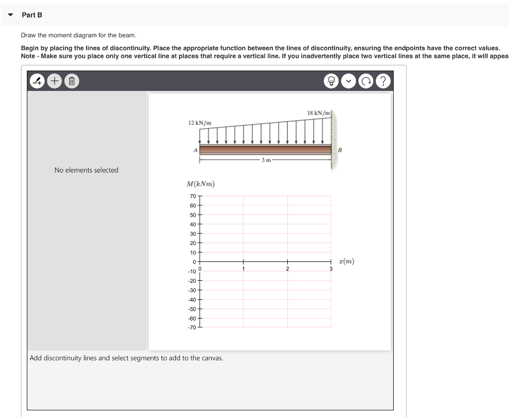
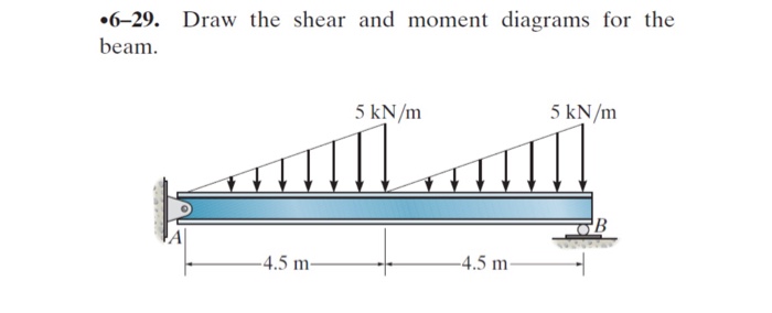
Assume the columns at A and B exert only vertical reactions on the pier. 629 Draw the shear and moment diagrams for the beam. Make sure you place only one vertical line at places that require a vertical fine.
Ay 75a 3 5 b - 23 0 FBC 75 kN MA 0. Lecture 6 13 Example 4-13 The vertical distributed loading on BC FBD of member BC resultant force 9 kN Perpendicular to its axis 9kNcos 45 o 6364kN Along its axis 6364kN4243m 15kNm Using these results V M diagrams are shown 796 kN 477 kN 675 kNm 225 kN 3 kNm 796 kN 477 kN 675 kNm 159 kN 159 kN. Circlearrowleft sum M 0quad -200-M0quad M-200lbft M 0.
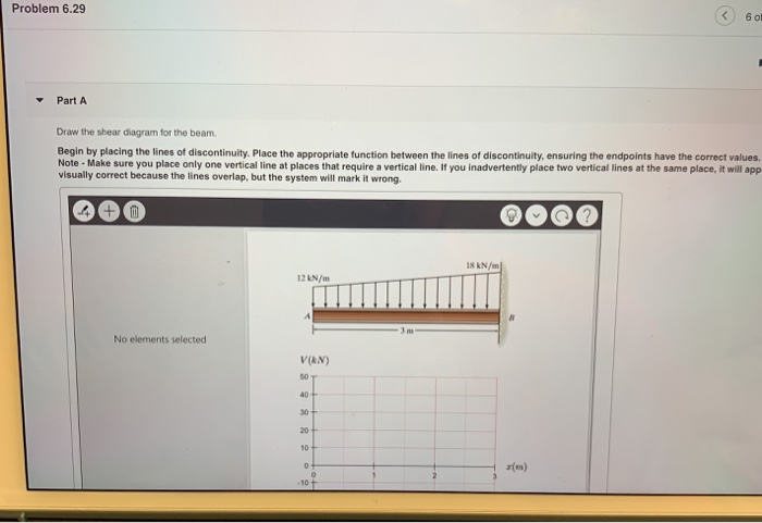
Q 271 728 N 71. A a Shear and Moment Diagram. 18 kNm 12 kNm B - 3 m Prob.
P kN L2 L2 A B. Shear Force and Bending Moment Diagrams SFD BMD VM-17 Shear Force Diagram SFD. Taking moments of the forces about A we get 4 120 Rg x 8 10 x 4 x 1 10 KNm A mme B a 1m -3m- 8 m- 4 m- 25 kN 15 kN 1.
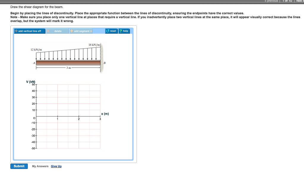
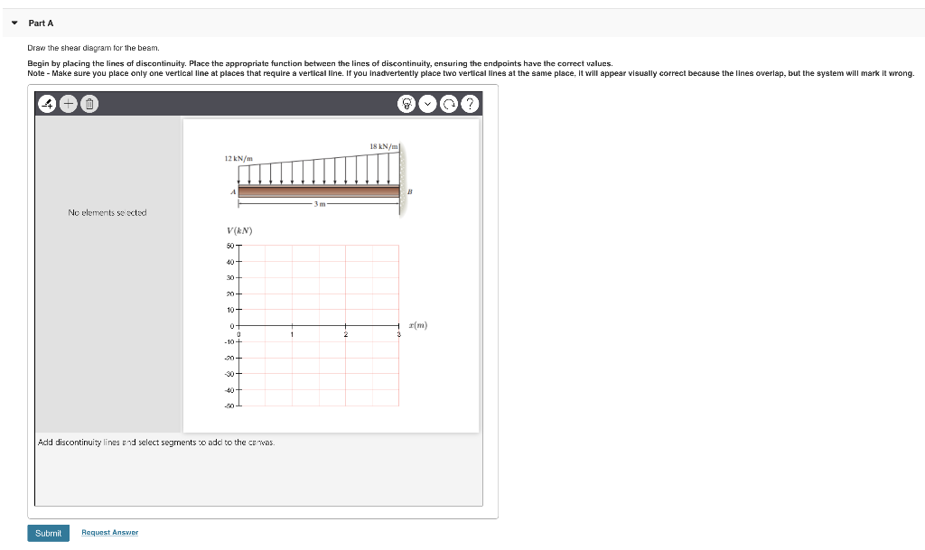
FBCa 3 5 b2 -. Enter the email address you signed up with and well email you a reset link. Problem 629 5 of 7 Part A Draw the shear diagram for the beam Begin by placing the lines of discontinuity.
Draw the shear and moment diagrams of the beam shown. 10kNm 1m 1m 3m Ans. Draw the shear and moment 1 m 1 m 15 m 15 m 1 m 1 m diagrams for the pier when it is subjected to the stringer loads shown.
Draw The Shear And Moment Diagrams For Overhang Beam In Fig 6 16 A Holooly. 20ft. Introduction Notations Relative to Shear and Moment Diagrams E modulus of elasticity psi I moment of inertia in4 L span length of the bending member ft.
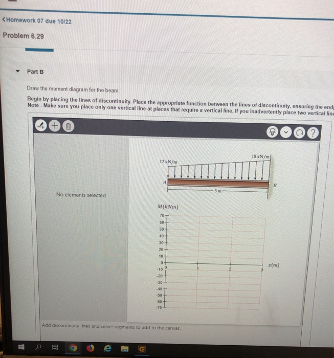
629 This problem has been solved. A short link at B is used to connect beams AB and BC to form the compound beam shown. Bending Moment Diagram BMD.
Diagrams for a simply supported beam of length 8 m and carryinga uniformly distributed load of 10 kNIm for a distance of 4 m as shown in Fig. Draw the shear and moment diagrams for the beam. Longitudinal spacing Of the nai Is is s 60 mm and that each nail is go mm l.
Locate points of contra flexure if any. A reinforced concrete pier is used to support the 60 kN 35 kN 35 kN 35 kN 60 kN stringers for a bridge deck. Beam Formulas With Shear And Mom.
SF just left of C 29 - 2 2 25 t. Place the appropriate function between the lines of discontinuity ensuring the endpoints have the correct values. Position of point of contra flexure from RHS 0375m Exercise Problems 25kNm 10kNm B 2m VM-75.
The vertical component of FBC is The shear and moment diagrams are shown in Figs. SF just right of D 16 -. B If P 20 kN and L 6 m draw the SFD and BMD for the beam.
Shear and moment diagrams and formulas are excerpted from the Western Woods Use Book 4th edition and are provided herein as a courtesy of Western Wood Products Association. Determine the shearing force in each nail. SF just left of D 20 - 2 2 16 t.
A B 2 m 2 m 10 kN 10 kN 15 kNm 2 m Prob. Draw The Shear And Moment Diagrams For Double Overhanging Beam Holooly. Draw the shear and moment diagrams for the beam.
Draw shear force and bending moment diagrams SFD and BMD for a single side overhanging beam subjected to loading as shown in the Fig. M 0. The diagram which shows the variation of bending moment along the length of the beam is called Bending Moment Diagram BMD.
Solved Draw The Shear Diagram For The Beam Begin By Placing Chegg Com
Solved Homework 07 Due 10 22 Problem 6 29 Draw The Shear Chegg Com
Solved Problem 6 29 5 Of 7 Part A Draw The Shear Diagram For Chegg Com
Solved Problem 6 29 Draw The Shear Diagram For The Beam Chegg Com
Solved Problem 6 29 Draw The Shear Diagram For The Beam Chegg Com
Solved Problem 6 29 Part A Dra The Shear Diagram For The Chegg Com
Solved Homework 07 Due 10 22 Problem 6 29 Draw The Shear Chegg Com
Solved 6 29 Draw The Shear And Moment Diagrams For The Chegg Com
0 comments
Post a Comment